
I became interested in electronics back in the 70’s but even though I also became interested in computers around the same time I never really looked at digital circuits in much detail. I recently thought it was about time I did. After going through my old ICs I found I had a number that seemed worth experimenting with. The first ones I wanted to experiment with are a 74HC14N hex inverting Schmitt trigger and CD4040BP 12-Stage Ripple-Carry Binary Counter/Divider.
The plan
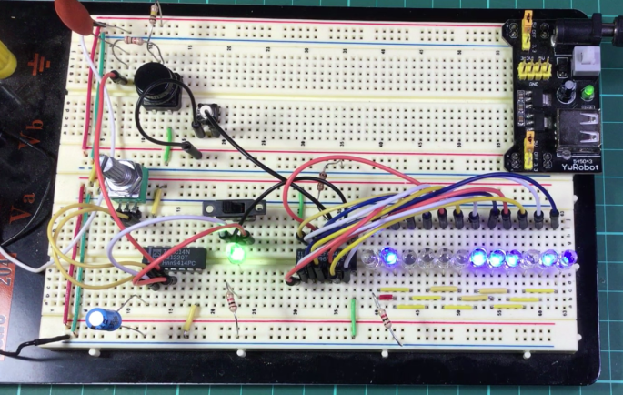
I wanted to set up a 4040 binary/ripple counterwith an oscillator on its input and a bunch of LEDs on the output so the LEDs would count and flash out the numbers in binary. As well as an oscillator generating a regular pulse I wanted to be able to switch over to a push switch to send pulses one at a time.
Initially I was going to use a 555 IC for the oscillator as I have seen other people using it, but when I tried it, it just kept stopping. Obviously I had something wrong. I read that a Schmitt trigger can be used an oscillator and knew it could be used in a debounce circuit so I gave up on the 555 and tried the 74HC14N which worked well.
About the 4040
I found the CD4040BP particularly interesting. When I read that it was a binary counter I assumed that there was some complex circuitry designed to produce the binary output, but after learning more I was surprised to findit is not that complicated. It is just made up of twelve flip-flops that are connected together internally. The output of the first flip flop is connected to the input of the next one. The output of each flip-flop changes state when the flip-flop connected to its input changes from high to low.The first flip flop is triggeredby a pulse from a pulse on its input. Because a flip flop only changes state, e.g. from low to high, or high to low, when the flip flop triggering it goes through a full cycle, that is, from low to high and back to low it results in the flip flop changing state at half the speed of the one triggering it. So pulsing the input results in the outputs changing state at half the speed of the one next to it.
Binary
Prior to dabbling with this circuit I did know a bit about binary and how to convert from binary to decimal and back, but this circuit has definitely given me a better understanding of it. In particular the way numbers in each column change when counting up.
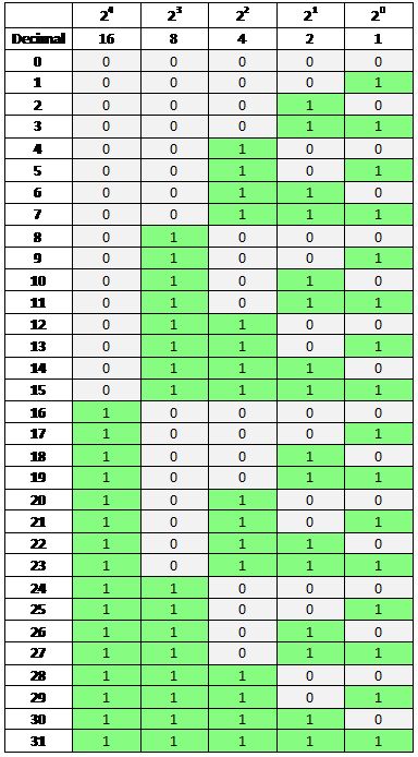
The table shows that numbers in each column are changing state at half the speed to those in the column to its right. The 4040 is not just dividing the frequency it is also counting in binary because it’s the same thing.
About the 74XX14
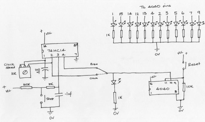
The other chip, the 74HC14N contains six (hex) inverting Schmitt triggers. A Schmitt trigger has an input and output. The output remains low until the input reaches a thresholdset in the IC. The output then goes high and remains high until the input drops to a threshold lower than the turn on threshold. The difference between the two thresholds is called hysteresis. This makes it useful to remove noise from digital signals. The 74HC14N is inverting so the outputs are high when the input is low and low when the input is high. This is the circuit that I came up with.
What’s going on
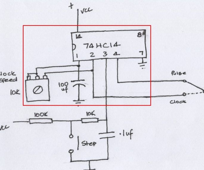
Starting with the 74HC14N. Pin 14 is connected to the positive supply and pin 7 to ground. A 10K pot and 100 µf capacitor are connected to one of the Schmitt triggers to make up the clock/oscillator circuit. The output (pin 2) from it goes to the pulse/clock switch.
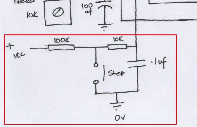
A 100K resistor, 10K resistor, .1uF capacitor, another Schmitt trigger and a push switch make up the circuit for the push switch to send out single pulses. The output of this Schmitt trigger goes to another connection on the pulse/clock switch. I originally connected a push switch without this other circuitry and quickly learned about the effects of not having debounce circuitry. I expected a single pulse to come out from the switch but instead the ripple counter was jumping numbers, perhaps up to 10 at a time indicating that there were lots of pulses. In other words my switch was very noisy and it turns out that they often are. The debounce circuit is working well enough for my circuit but it may not be ideal.
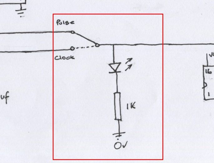
The next part of the circuit is the pulse/clock switch and LED. The switch is to allow me to switch between regular pulses or step through one pulse at a time using the press switch. The LED flashes with each pulse. The resistor is there to limit the current to the LED. 1K may be a bit high as my LED is not very bright.
Next is the 4040. Power is connected to pin 16 and ground to pin 8. The input goes into pin 10. Pin 11 is used to reset all outputs to low, that is in this circuit back to 0 on the counter. This pin is connected to ground via a 10K resistor and to VCC via the push switch.
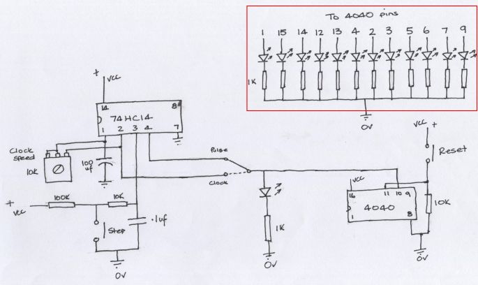
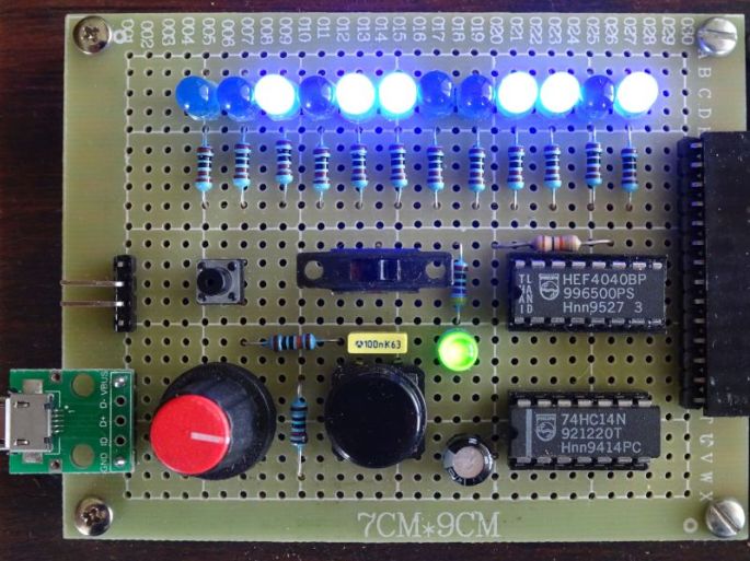
12 LEDs are connected to each of the outputs. Each LED has a resistor to limit the current. I don’t know that they need separate resistors. I initially tried with all the LED negative sides connected together and then connected to ground via a single resistor. It may be my imagination but when using 12 resistors it appears the brightness of each LED is consistent when there is one or all LEDs on at a time.
What’s next
Well that’s it for this circuit. It works, but it’s probably not optimal. It’s not particularly exciting but I I’ve learned something. The next stage I found more interesting when I connected it up to an old EPROM. Later I would like to come back to this and try to get it going with a 555.

I used the IC from a flip flap solar flower from the pound shop. it works perfectly and only three leads.
LikeLike
Hi Kevin, I thought about and probably should have used a 555 as it is not only an obvious choice but also have some. Your method an interesting and creative way to go. Always rewarding to try your own solution.
LikeLike