This thread has been locked.

If you have a related question, please click the "Ask a related question" button in the top right corner. The newly created question will be automatically linked to this question.

TPS71710 Overvoltage at startup

Other Parts Discussed in Thread: TPS71710

Hello,

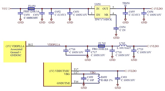
We have a design with a TPS71710 producing 1V from a regulated input voltage of 3V3. We use the 1V to power an ARM processor core.  We have made two production (prototype and a first production). The prototypes are working correctly but the production units not. When we apply the power supply the 3V3 rise relatively slowly but the 1V rise to around 1V5 and then decrease to 1V. On the prototype the rise of the 1V is slow. We have try different value for C654 (capacitor on NR pin). It work with 100 nF but it is really big and creaste power up sequencing issue. With 10 nF it doesn't work correctly. We have also short circuit L702 but this doent' change anything. We have not find any solution. As you can see hereunder the NR pin voltage has also an overvoltage so we suspect an issue inside the integrated circuit. We know that part used for prototype were not from the same as part for production. Is it possible that TI has change somethink in the TPS71710 to correct an issue or for any other reason ?

Here is the schematic

This is a copy of the scope (trace 1 is NR pin and trace 2 is LDO output voltage) with C654 of 10 nF

for the prototype (working correctly)

and a copy of the scope for the production unit (not working correctly) with C654 of 10 nF

Maybe this issue is also reltated with this one http://e2e.ti.com/support/power_management/linear_regulators/f/321/t/148668.aspx but I am unable to disconnect the load (BGA soldered on the same PCB). So I have not yet found a solution.

Thanks in advance for your help

  • Hello,

    To prevent the overvoltage at start up for this part I would advise either enabling the part after Vin or to increase the ramp rate of Vin at startup. Please let me know if this does not solve your problem.

    Regards,

    David

  • Hello David,

    I have modified my board to enable the TPS71710 only after the Vin is stable. To do that I have connected the TPS71710 enable pin to the power good of the Vcc (3V3) regulator. But this modification doesn't solve the issue. As you can see on the scope copy hereunder the output voltage has an overlvoltage of up to 1V67 and then decrease to 1V (this take around 2 ms).

    Scope copy (trace 1 is Vcc = 3V3 and trace 2 is TPS71710 output voltage)

    Increasing the ramp rate of Vin is not possible. It is already relatively short (around 400 µs).

    Is there a solution to this issue ? Could you explain us why the prototype was working correctly and the production not ?

    Regards,

    Didier

  • Hi Didier,

    For a 400us startup, I would recommend increasing the CNR cap to 0.1uF or higher.

    As to why the prototype works correctly and the production unit does not I am still looking into that.

    Regards,

    David

  • Hi David,

    With a 100 nF there is no overvoltage but the power on delay is then 150 ms. This create an issue on the power sequencing for the processor. Having a power startup voltage of 150 ms is not a normal value. Is there another solution ?

    Thanks

    Didier

  • Hi Didier,

    I'm not sure if it will work with your application, but we have sometimes seen no CNR cap shows only a slight overshoot and not a large overshoot at start-up.

    Regards,

    David

  • Hi David,

    Without CNR capacitor the overvoltage is still 1V4. It is not acceptable for our application (processor power supply).

    It seems that the TPS71710 is not working properly abd that we must change our design to use another part. There is no pin to pin equivalent which mean we will need to made a new pcb which is a big issue.

    Are you sure there is no solution to solve this overvoltage without having a really long startup time ?

    Thanks for your help.

    Regards,

    Didier

  • Hi Didier,

    I found in the lab that if you enable after Vin with a 10 nF CNR cap then there should be no overshoot. The only other solution would be a faster start up time. Please let me know if this does not work.


    Regards,


    David.

  • Hi David,

    Thank you for testing this. I have made the same (Enbale when Vcc is stable and CNR of 10 nF). In this case I have no overshoot. If I connect the Enbale to Vin or place a 1 nF CNR or no CNR then it doesn't work. The voltage need around 5 ms to stabilise which is an issue for us on the power up sequencing of my processor. Here is a copy of the startup with trace 1 = 3V3 input voltage and trace 2 is 1V output voltage

    From my personnal experience this doesn't seems to be what we expect from a LDO regulator (which normally start quickly) and also with the instability above, I have the feeling that the TPS71710 part is not working properly. Personnally I will not use it for future design and I think TI would do well to replace it by a new design.

    Finally I founded a solution with a LDO made by another manufacturer and available from stock on Newark/Farnell with the same footprint and pinout. This part doesn't need a CNR capacitor and work perfectly without any overvoltage and with a really quick startup. This part also work correctly without the enable which permit us to simply rework the part we have already produce. Here is a copy of the scope for this LDO (1 = Vin 3V3 2 = Vout 1V):

    Once again thanks for your help and time.

    Best regards,

    Didier